A torque request, not a direct connection
Open the throttle and a control system interprets your input. Depending on the design, it may translate grip position into requested torque, power or a mapped combination of variables. Battery limits, motor speed, temperatures and vehicle-control interventions then constrain that request. The resulting response is therefore calibrated behaviour, not an unavoidable property of an electric motor.
That distinction explains why two electrically powered motorcycles can feel very different at a small throttle opening. One can deliver a steep torque gradient; another can offer a gentler initial response. Neither description alone tells you the maximum capability. What matters to the rider is whether the response is predictable while the machine is leaned over, crossing a bump or transferring weight.
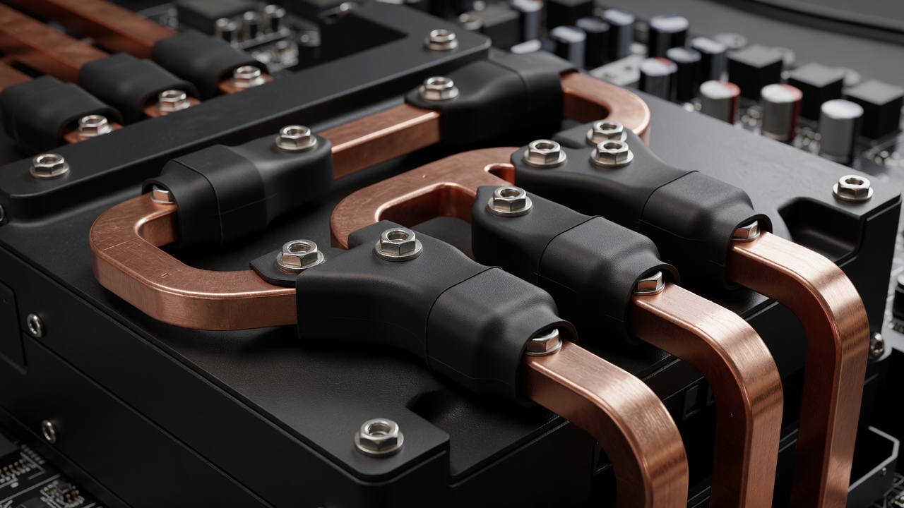
The inverter makes the magnetic timing
A traction battery supplies direct current. The inverter uses semiconductor switches to apply controlled voltages to the motor phases, producing the currents that create a rotating magnetic field. Silicon insulated-gate bipolar transistors, or IGBTs, and silicon-carbide MOSFETs are examples of switching technologies. Device choice affects loss, switching behaviour, packaging and cost; a material name by itself does not establish system efficiency.
Field-oriented control, often shortened to FOC, is a common way to manage motor current relative to rotor position. In simplified terms, it separates current associated with magnetic flux from current associated with torque. Current sensors and a rotor-position sensor, such as a resolver or encoder, support this calculation. Sensor accuracy and control tuning affect smoothness as well as fault detection.
Why phase current and battery current differ
Motor phase current is not interchangeable with battery current. The inverter transforms electrical conditions while energy moves through the drive. At relatively low motor speed, substantial torque-producing phase current can coexist with lower battery current than a simple one-to-one comparison would suggest. Losses, modulation and the motor operating point all matter.
For comparison work, ask where a current was measured and whether it is a peak, average or root-mean-square value. Root-mean-square current is useful when considering resistive heating. A dramatic current figure without its measurement basis tells you little about repeatable wheel performance. Likewise, an inverter current rating is not automatically a complete motorcycle rating.
Speed changes the available torque
As a motor turns faster, it generates a voltage opposing the applied supply, commonly called back electromotive force or back EMF. Eventually the available DC bus voltage limits the current the controller can establish. Below that region, a drive may maintain approximately constant torque within its current and thermal limits. At higher speed, torque generally falls as available voltage becomes restrictive.
Field weakening extends the useful speed range by adjusting magnetic conditions, but it is not free extra performance. It can require additional current and introduce efficiency or thermal penalties. Permanent-magnet synchronous motors and induction motors handle flux differently, so their control details are not identical. Compare complete operating maps rather than assuming one motor label guarantees the best result.
Final drive connects the motor to the road
Reduction gearing multiplies motor torque at the wheel, after mechanical losses, while increasing motor speed for a given road speed. A shorter ratio can sharpen corner-exit response yet bring the motor closer to its speed or voltage limit on a long straight. A taller ratio can do the opposite. The useful choice depends on the circuit, motor map, tyre radius and required speed range.
Chains, sprockets, bearings and alignment also influence how cleanly torque arrives. Mechanical clearance and driveline compliance can become noticeable when torque changes direction between drive and regeneration. Software can soften that transition, but calibration cannot compensate indefinitely for poor mechanical condition. Manufacturer maintenance instructions remain the correct reference for adjustment and inspection.
| Claim | Useful follow-up |
|---|---|
| Peak torque | At the motor or wheel, at what speed, and for how long? |
| Peak power | At what voltage, state of charge and component temperature? |
| High efficiency | At which torque-speed point, and including which losses? |
What a useful development test records
A dynamometer, or controlled load machine, can help map torque and speed under repeatable conditions. A strong test record includes DC voltage, battery current, phase-current interpretation, motor speed and relevant temperatures. Wheel measurements must account for the chosen test setup rather than being casually mixed with shaft measurements. Logging timing also matters when comparing transient events.
Standards such as ISO 26262-12 address adaptation of functional-safety concepts for motorcycles; they are not performance scorecards. Their value here is a reminder that intended behaviour and fault behaviour both need engineering attention. The best traction system does more than make a large number: it delivers a clear request, a controlled response and a safe reaction when something stops agreeing.
Translate the drive vocabulary
DC bus: the inverter's direct-current supply rails. FOC: current control referenced to rotor position. Back EMF: voltage generated by a rotating motor. Field weakening: control that extends speed capability by reducing effective flux.